Does anyone have the maintenance manual and service manual for a MAzak SQT18m it has T-Plus control. I think I have all the others in PDF format it anyone is interested.
↧
Maintenance manual request for SQT18m I have other manuals in PDF
↧
sending gcode program to Mazatrol m32
We just recently got a Mazak vtc16c mill at work and I have been running it a little for a few weeks. I have programmed it with mazatrol and I also used Bobcad to make a few programs with gcode that I drip feed it by using the tape button. All this works fine. We also have camlink and I can save the mazatrol files from the mill to a computer and I can also save the gcode files that are on the machine to a computer using the camlink. One thing I cant get it to do is accept a gcode file from bobcad and store it on the machine. I have given the bobcad file an .eia extension but still no luck. I know the machine will only accept a small file but I tried a really small file but still no luck . Anybody have any ideas?
↧
↧
Backside threading issue - Nexus Matrix Control
Was hoping someone might be able to take a quick look at this attempt to single point threads on the backside of a part and let me know what I am doing wrong. Tried all types of scenarios with no luck. I keep getting a 740 illegal angle in first sequence error.
Mazak QTN-100 Nexus Matrix fusion control.
Basically I am turning a shaft .250" with a .375" shoulder and 12-24 threads behind it. Trying to get it all in one work holding. Please ignore how long the threaded area is. It will only be .225" long and the story behind that was clearing it out trying to understand what I was doing wrong in the control.
I was wondering if I should try doing it without the "Back" Option using "out"?
![]()
![]()
Mazak QTN-100 Nexus Matrix fusion control.
Basically I am turning a shaft .250" with a .375" shoulder and 12-24 threads behind it. Trying to get it all in one work holding. Please ignore how long the threaded area is. It will only be .225" long and the story behind that was clearing it out trying to understand what I was doing wrong in the control.
I was wondering if I should try doing it without the "Back" Option using "out"?


↧
Mazatrol Programming Help!
SQT-10m with T-Plus control. I have a part here that I have put a 1 1/32" hole about 2" into the part. When I do side 2 I need to drill a 1 5/16" hole to meet up with the 1 1/32 from the other side. Now I know someone will asked why I don't put both holes in from the same side. For various reasons right now I can't but the main reason is I don't have a 1.032" drill long enough. My question is how do I define that hole from the other side. The problem I'm having is that the holes are put in from both ends but I need to go in with a boring bar and profile the shape using both bores. Right now it thinks that 1.032" bore is solid. I had did this part before and I did put both bores in from the same side but I was having chip problems because I couldn't drill deep enough and so that's why I did it from the opposite so it would become a through hole. If I do these parts again I probably pick up a spade drill. But for now this is what I have to work with. I tried to define the shape with the MTR function but I have never used that before and I had no luck.
Some input would be greatly appreciated.
Thanks Guys!
Some input would be greatly appreciated.
Thanks Guys!
↧
V515/40 Spindle lube issues
1995 Mazak V515/40
Back in November we started to get a lot of noise from the spindle, to loud to stand at 3k so we statted to investigate. Machine is fairly new to us and always seemed loud from day one but this was way too loud. Dug in and the spindle lube system which uses lube usa air mixing valves to blow air and oil onto the spindle bearings and gears was in bad shape. Previous owners ran dirt for air and terrible way oil. Come to find out both systems were heavily contaminated so we cleaned everything and replaced the pricy air metering valves/lines to bearings. Have everything set back up by Lube USA spec and it seems to move a ton of air. It's loud, like a blow gun wide open inside the head. Our 10hp piston compressor (40cfm) running this machine solely kicks on every 3-5 minutes. It seems like a ton of air but matches what the book calls for.. machine was originally set up with mixing valves choking air more but we feel if the bearings aren't already shot that the extra air wouldn't hurt. Surely it wouldn't blow the lube right off its intended spot.
Does anyone have feedback on how much air their 515 consumes? Not wanting to buy a new compressor but we have various other needs for the compressor already and really stress it at times.
Thanks in advance,
Ethan
↧
↧
VDI tooling questions
I just purchased a SQT18M. I am looking at additional tooling. Will any VDI40 tooling fit and interchange. Cana tool holder from a Okuma fit a Mazak are there differences? I see tooling listed in the catalogs saying VDI40 but then it has brands in addition?
Also where is the tool height adjustment?
Also where is the tool height adjustment?
↧
Multiplex 620 error
G'day all,
I have recently purchase a multiplex 620 with T32/6 controller very cheap because it hadn't run for quite a while. I have finally had time to power it up and after fixing the problem with the monitor I get a system check error. I have all the codes and most of the manuals but no mention of this error. Any ideas???:rolleyes5::rolleyes5::rolleyes5:
I have recently purchase a multiplex 620 with T32/6 controller very cheap because it hadn't run for quite a while. I have finally had time to power it up and after fixing the problem with the monitor I get a system check error. I have all the codes and most of the manuals but no mention of this error. Any ideas???:rolleyes5::rolleyes5::rolleyes5:
↧
Getting new mill VCU500C or NEXUS 530C-II HS or Haas VF-3?
Considering a Mazak VCU 500 or NEXUS 530C-II HS. also in the running is a Haas VF-3
I tend to steer away from the VCU because of the stationary table and reduced rigidity in regards to the nexus which can run a 50 taper. we will be running large drills and doing moderate/heavy milling
It's to replace a 4020 fadal.
Thoughts?
I tend to steer away from the VCU because of the stationary table and reduced rigidity in regards to the nexus which can run a 50 taper. we will be running large drills and doing moderate/heavy milling
It's to replace a 4020 fadal.
Thoughts?
↧
Mazak battery replacment on T-Plus and M-Plus
For the first just replaced batteries on both machines 1997 VTC16 and 1998 SQT250.
What I found strange was that after disconnecting old batteries I did not see any alarms... is this normal?
What I found strange was that after disconnecting old batteries I did not see any alarms... is this normal?
↧
↧
General question for measuring Ohms in ground circuits of Mazak machines.
Hi all,
Here is the essence of the longer drawn out question below:
When I measure continuity through a G24 wire to machine ground, I get two different readings when I swap the leads (pos. and negative) on my points that I am measuring. The electrons flowing one way through the machine yield a different resistance than the other way. :crazy:
Also, does anybody know what the difference between P24 and I think it was +24N is in Mazak machines?
I have never differentiated between the two since they are both positive 24VDC.
Battling my issue on a QT-15 that doesn't have the 24V system grounded through sections I cannot identify yet, I came across a phenomenon that someone here might have encountered before.
I am trying to fix the indexing on one of our H-400 horizontal mills. It has a MPS-510 M/T controller.
Measuring ground continuity between the labeled G24 wire on my 0°search switch in the left door to ground yields
0.8 K Ohm when I connect the negative lead to the wire terminal and the positive to machine ground,
and 0.2 Ohm when I connect the positive lead to the switch terminal and the negative lead to machine ground.
Shouldn't it be the same? I mean it completes the same circuit.
The same phenomenon occurs on the QT-15. I'll double check my other machines, but maybe someone has an explanation for this.
Maybe I simply don't understand some basic principles of how resistance is measured.
Thanks for any input.
Oliver
↧
T+ Program transfer
Finally got everything I need to transfer programs out of my SQT15MS.
I tried connecting a PC to the control with Mazview, but in the setting I'm not having anything show up under "Communications Port".
There are two 25pin connectors under the control, and I've tried both of them. Just using a standard RS232 25 pin to USB cable.
Anything else I should be doing?
Attached are some relevant photos. The website photo claims those are the settings needed for DNC (what does that stand for?)
Thanks for any help.
![]()
![]()
![]()
![]()
I tried connecting a PC to the control with Mazview, but in the setting I'm not having anything show up under "Communications Port".
There are two 25pin connectors under the control, and I've tried both of them. Just using a standard RS232 25 pin to USB cable.
Anything else I should be doing?
Attached are some relevant photos. The website photo claims those are the settings needed for DNC (what does that stand for?)
Thanks for any help.


↧
How to adjust spindle ramp and decel speed on T-Plus SQT18?
How do you adjust the spindle ram up and decel speed? I am running off of limited power and I would like to slow the ramp and decel times. My circuit should be fine at 120 amps but I want to dial it back in case I have another machine come on at the same time.
I assume the setting will be on the VFD but will I have to change anything in the control also?
Thank you in advance.
I assume the setting will be on the VFD but will I have to change anything in the control also?
Thank you in advance.
↧
Machine Purchase Help!
Hello People,
We produce various types of batch qty. (100-150 nos.) with different sizes.
At present we have 3 CNCs 2 VMCs. But now we are majorly facing setting times, man power, material handling and other similar issues. where we have tolerances for all parts 15-20 microns
We are now thinking of getting Multitasking machines, Mazak Integrex j-200S or DMG Mori CTX Beta 800 TC or Okuma Multus B200 II (750)
Which do you people recommend? I have read on this forum about Okuma problems & mostly i am getting away from Okuma most probably.
It would be great if you could share your experiences. (Easy Working, Downtimes/Breakdowns, Services, what should i look out for, etc. )
↧
↧
T-Plus alarm 25
So I bought a 1996 SQT-18M and put it in my barn. I had the power co run 3 Phase 208v service. Just got everything hooked up and turned on my new to me machine. After checking transformer taps, and getting the phasing correct, I get alarm 25 main power supply malf on the screen. I looked in the cabinet and the drive is flashing 65. The book says power supply detected surge errors.
Any idea where to look would be great. When I looked at the alarm history, it also had a 204 spindle controller malf. Not sure which one caused the other if at all. Any help is much appreciated.
Thanks Chad
Any idea where to look would be great. When I looked at the alarm history, it also had a 204 spindle controller malf. Not sure which one caused the other if at all. Any help is much appreciated.
Thanks Chad
↧
Help needed - Eia control of chamfer tool driving too deep
Hi all
Hopefully someone can point me in the right direction...
I am running the VQC with M2 Control in drip feed mode which I have been doing for a while and all has been going as well as can be expected.
I'm using Bobcad for my Cad/ Cam and that has been working fine too.
The exception is when I try and do a chamfer. I am setting a very small edge break - 0.2mm but the tool is driving in deeper and giving me a 3mm chamfer.. I manually adjusted the Gcode to only drive in 0.2 from the top (so ignoring the 45 degree section on the tool) and it gave me the desired results in the simulation and on the part. The Chamfer is the last op and essentially junking the part.
I carried out a trial in the Cam tonight. I set up a basic cube with a small chamfer and the G code is coming out as I expect and putting the tool tip where it should be. The simulation (both Bobcad and 3rd party) are showing it is sending the right commands.. so I am confident the cam is giving all the right commands and positioning the tool to compensate for position, and instructing the depth to accommodate the offset. (I analysed the code for the part and it looks fine too)
The code below is the trial piece I mentioned above. It is a 0.141mm deep Chamfer (0.2mm flat on chamfer) on a 50x50mm square block with Zero point set in the middle of the top surface. I have set the tool to be 1mm from the edge of the part, which also means it goes down 1mm before it engages the part. Total depth of tool tip is thus -1.141mm from datum (underlined below).
%
O200 (CHAMFER TEST.EIA)
(SAT. 02/18/2017 09:21PM)
( MAZATROL CAM M-2)
( T1 CHAMFER MILL , DIAMETER = 20. , LENGTH = 127.)
G90 G80 G40 G49 G17 G94 G00
(Machine Setup - 1 Chamfer Mill)
(FEATURE 2 AXIS)
T01 M39
M06
( T01)
S3000 M03
G54 G90 X26. Y-26.
G43 Z25.4 M08
Z5.08
Z2.54
G01 Z-1.141 F109.537
X-26. F219.075
Y26.
X26.
Y-26.
G00 Z5.08
Z25.4
M09
M05
G91 G28 Z0.
G91 G28 Y0.
M02
M30
%
So next I start to think I have some form of compensation going on in the CNC... I checked this and it is set to Zero in the Tool Data page (as I had entered). In addition, I assigned the tool as an endmill to emulate the same characteristics of an endmill as the endmills are working perfectly. The Gcode doesn't care what tool is actually in the pocket as long as it has a tool offset it does whatever the code is programmed to do. The problem still occurred.
I tried a different tool and checked the tool length offset/ remeasured tool length etc, but that all looks ok.
I also checked the tool offset page and they are all zero as well (never entered anything in these cells)
I'm thinking there may be another parameter that I am missing or an compensation somewhere that is pushing the tool into the workpiece.
Id prefer to not have to manually adjust code to accommodate for something that should be an easy fix.
Any ideas are much appreciated.
Cheers
Mick
↧
Advice needed: Looking at a vtc 16b with M32b control
I have no experience with Mazak and this machine (95 vtc 16b with m32b control) has become available:
Questions:
Are there any more common issues that I should be looking out for with this model?
Do I have anything to worry about with this control ( I will be mostly programming with cam and sending via rs232)
Job shop type work with the occasional small mold inserts(any control issues as far as 3d surface machining).
Thanks for any help!
↧
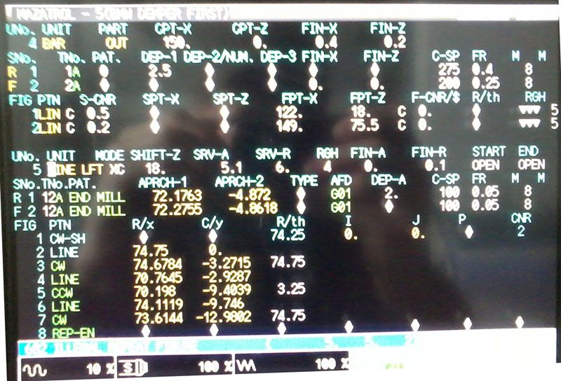
Clockwise shift programming
Trying to make a 36-1 trigger wheel. I got the tooth shape right it seems, but I get error message "682-Illegal repeat figure". Have tried multiple variations but no luck. I've looked in the manual but I am not sure what the radius on the CW-SH line should be. Is there any rule to that ? The CNR should be 36, but I just tried with 2.The figure starts in the middle of a tooth, moves to the right and ends in the middle of the next tooth.
![]()
↧
↧
Aligning turret tool position. Cannot bore, drill etc. SQT-18MS
Hi there,
does anyone have a kind of instructions or turet plans or at least the manufacturer, for aligning the turet tooling postion. To clarify what i'm saying - the drill tip is below the z-axis of spindle, and same are the other tooling, so the problem is not in holder.
We have loosen all the bolts, pushed with the big piece of rod, but anything happens. Appreciate for every comment
↧
Mazatrol- another "shift" program question
This unit will only machine this shape twice, even though the repeat value is 16. Tool shape shows 16 figures, but Tool path, only 2. WTF?![Click image for larger version.
Name: Clip02.jpg
Views: 11
Size: 19.6 KB
ID: 191809]()

↧
Renishaw Inspection plus & using coordinate rotation
Hi Everyone,
I have followed the forum for a number of years as an observer only.I really appreciate all the great information provided. This is the first time I have posted a question on the forum.
I have successfully used Inspection plus to measure the angle a part was sitting on and rotate the WPC of a program for machining. The trouble I have is once the part is machined the ability to measure with the probe is not permitted with the coordinate rotation active.Does anyone have experience measuring while G68 is active? What controllers if any permit this to occur? Can anyone explain what is the difference between being able to machine with rotation active but not probing?
The Machine is a 3 axis Mazak VCN 700 E with a Matrix Nexus controller and the probe is a Renishaw OMP60
Thanks
↧